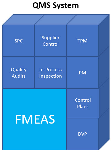
How FMEAs Can Be the Cornerstone of ISO 2001:2015 Compliant Risk Based Quality Management System
Summary & Conclusions
There are several key differences between ISO/DIS 9001:2015 and its predecessors. One of the differences is the standard incorporates risk-based thinking in requirements for the establishment, implementation, maintenance and continual improvement of the quality management system. The Design Failure Modes and Effects Analysis (Design FMEA) and Process Failure Modes and Effects Analysis (Process FMEA) are two powerful processes for defining and managing risk within any quality management system.
This paper will show that the Design FMEA, Process FMEA and the tools which they are integrated with can be the foundation of a risk-based, fully compliant ISO/DIS 9001:2015 Quality Management System (QMS). For the FMEAs to fulfill their critical role in the QMS, they must be done correctly. The paper will identify common mistakes made when performing the two FMEA types that if made will severely inhibit the effectiveness of the FMEAs as well as the QMS.
Companies who have corrected the mistakes identified in the paper have experienced tremendous financial benefits with one major facility experiencing an average weekly cost savings of $144,000 per week after implementing the required changes in their FMEA processes for only nine months.
What Is Risk?
Risk has two components. The first component is the severity of harm experienced when an objectionable event when it occurs. The harm can take on many forms including financial loss or in the worst case bodily injury including death. The second component of risk is the probability of exposure to the individual harm types when the objectionable event occurs. Since there can be can be multiple consequences of an objectionable incident, there are often multiple severity of of the event occurring. Consequently, one can reduce the risk of a particular event by taking steps to mitigate the consequences when the event occurs or to reduce the probability of the event.
Sources Of Risk
The ISO 9001:2015 standard provides numerous requirements targeted at the reduction of three sources of risk that companies’ face when attempting to design and manufacture products. These three sources of risk are:
- Incomplete and/or incorrect definition of design inputs
- Creation of design outputs that are inadequate to meet the design inputs
- Manufacture of products that do not meet the design output specifications
Fortunately there are two processes that if used correctly can significantly reduce the risk due to the three sources identified as well as provide the foundation for a compliant ISO/DIS 9001:2015 Quality Management System. The two processes are the Design FMEA process and Process FMEA process.
Design FMEA Process
One common misconception is that the Design FMEA process is a brainstorming activity to identify and prioritize failure modes. The “modern” Design FMEA process is a structured risk assessment of the adequacy of the Design Outputs in defining a product which will meet the Design Inputs. Although failure modes are identified during the process, the fundamental objective is to assess the risk of releasing a product which is manufactured to meet the Design Output requirements.
The most important column of the Design FMEA is the “Design Requirements” column (Figure 1). This column is used to capture the Design Inputs. If a company makes an error in defining the Design Inputs the mistake will not be known until the product is not purchased or the product is failing in the field. ISO 9001:2015 has sixteen requirements that are designed to assist in the proper definition of Design Inputs.
Proper definition of Design Inputs begins with understanding the intended use of the product. When investigating the intended use it is critical to include all requirements and not just those involving function. Some of the requirement types to be considered are:
- Function
- Safety
- Regulatory
- Environmental
- Reliability
- Ergonomic
- Sensory
- Manufacturability
In total, there are eighteen types of requirements that should be considered for inclusion while investigating the intended use. The results of the intended use investigation are critical in establishing the acceptance criteria for the Design Validation Plan that will be used in combination with the Design Verification Plan to assess the adequacy of the Design Outputs.
Once the intended use has been defined, a set of Design Inputs that the designer(s) will design to must be defined. When defining the Design Inputs it is important to recognize that some of the requirements defined during the intended use investigation might compete with each other, conflict with each other or are beyond the limits of current technology. There is a high likelihood that it will not be possible to define a set of Design Inputs that will define a product that will meet all the intended use requirements defined. The Design Inputs must be optimized to provide the best Risk/Benefit ratio for the customer. One of the best methods for accomplishing this task is the Requirements Risk Assessment™.
One common mistake made when performing Design FMEAs is to turn the first column of the Design FMEA into a bill of materials and then list the functions of each component in the first column. It is important to remember that the customer is purchasing what they believe the product will do for them and not the components that make up the product. If it were possible to create a product that met all the customers intended use requirements but only consisted of an empty enclosure there is a high likelihood the customer would have no problems with the product.
The second mistake that is becoming more common is the creation of too many DFMEAs for a single product. The DFMEA method that leads to this mistake begins with breaking the product down into structure elements consisting of the system, subsystems and components that make up the product. Individual DFMEAs are then created for each structure element.
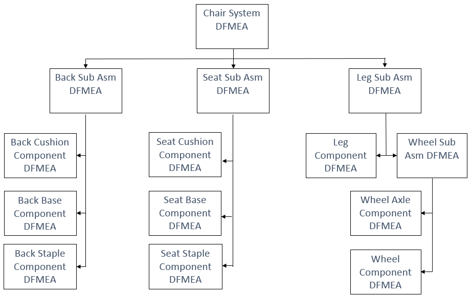
Figure 2: Too Many DFMEAs for One Product
Figure 2 shows the fourteen DFMEAs that the methodology requires be created for an office chair “system” and its thirteen elements (four subassemblies and nine components). Each element DFMEA must have requirements defined for its first column.
There are many shortcomings to this approach including a tremendous reduction of efficiency of the DFMEA process by forcing the engineers performing the DFMEA to spend considerable time defining artificial requirements for subsystems and/or components that are already completely described at an adequate level of detail using dimensional and material specifications.
ISO 2001:2015 does not require the definition of design requirements for each of the subassemblies and components that make up a product. The standard requires only that the Design Outputs of the design process define a product which will meet the Design Inputs. For this reason, the number of DFMEAs should be based on the number of design groups involved in the design of the product so that each group can assess the adequacy of their Design Outputs in meeting their Design Inputs. The number of subsystems and components defined by the Design Outputs of each group should have no bearing on the number of DFMEAs required.
Once the Design Inputs are defined, it is important to define how the inputs can fail to be met and the consequences of not meeting them. A numerical value indicative of the level of harm due to the consequences is placed in the Severity (Sev) column (Figure 3).
The Failure Cause column of the Design FMEA describes the condition of the Design Output that if present can lead to the Design Input not being met. The Design Controls column contains the method(s) that will be used to verify the adequacy of the current Design Output in meeting the Design Input. The results of the performance of the Design Control(s) are used to determine the probability of exposure to harm due to the Design Input not being met because of the Design Output condition identified in the Failure Cause column. A rating corresponding to the probability is placed in the Occurrence Rating (Occ) column.
A common mistake made when performing the Design FMEA is to determine the Occurrence Rating based on the probability of the Cause and not the probability of the Failure Mode due to the cause. Unless the Failure Mode always occurs when the Cause is present, this mistake leads to an assignment of a risk level for the DFMEA Failure Mode/Cause combination that is too high.
With the Severity of harm due to the Failure Mode and the probability of the Failure Mode due to the Failure Cause defined, it is now possible to determine the potential risk described by the row of the Design FMEA. A Risk Table (Figure 5) is used to categorize the various levels of risk through the use of symbols. These symbols are placed in the Class column of the Design FMEA to indicate the risk due to the row of the Design FMEA. If a Severity and Occurrence combination has no symbol it means that the risk described by the combination is considered acceptable.
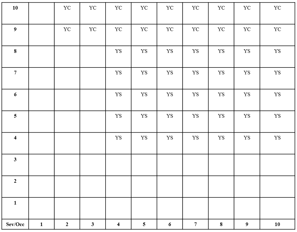
Figure 5: DFMEA Automotive Risk (Class Symbol) Table
The Risk Table is also used to develop a Risk Policy for the design and manufacture of the product. As an example, a company might take the position that they will not release a design for manufacture that has any rows of a Design FMEA with a “YC” (Safety Issue) class symbol which would indicate that an event affecting safety could occur when the product is manufactured to specification.
Risk Tables can take on different forms (i.e. numbers of rows and columns, symbol types). The previous Risk Table is used in the automotive industry.
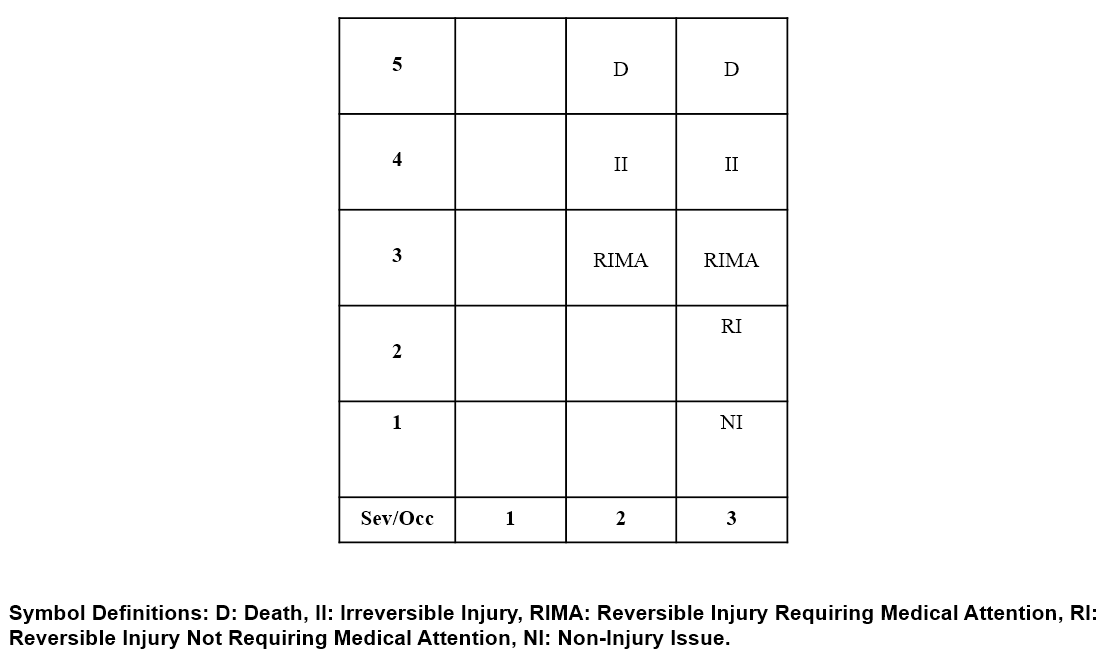
The Risk Table in Figure 6 was used for determining Class Symbols for Design FMEAs covering both spinal implants and a late stage cancer treatment. Due to the differences between the products, the same Risk Table was used for Class Symbol determination but the Risk Policy on what was acceptable was considerably different since more risk is acceptable for cancer treatments than spinal implants since significantly more harm will occur if no action is taken for the cancer versus the spinal condition.
The Risk Class and Occurrence Rating are used to determine the priority of the elements of the design to be worked on first (Figure 7). All lines of the Design FMEA with a Class Symbol present must be worked on.
Although the Detection Rating (Det) and Risk Priority Number (RPN) columns are present in the Design FMEA they play a very limited role in prioritizing what to work on.
Elements Of ISO 2001:2015 Supported By The Design FMEA Process
When performed correctly, the Design FMEA process forces a company to document the product development process from the definition of customer requirements through to the release of the design to manufacturing.
When combined with the quality tools it drives, the Design FMEA process directly fulfills or provides support for meeting the majority of the requirements found in following sections of the ISO 9001:2015 standard:
- 8.1 Operational planning and control
- 8.2 Determination of requirements for products and services
- 8.3 Design and development of products and services
- 8.4 Control of externally provided products and services
- 10.0 Improvement
Process FMEA Process
The Process FMEA process is a structured risk assessment of the adequacy of the Process and Process Controls in manufacturing a product which will meet the Design Output requirements.
The Process FMEA process begins with the definition of the Process Path (Figure 8). The first step of any process used in the production of a product is the receipt of purchased materials. After the receiving steps are identified, every processing, storage, transport and inspection step that can affect the quality of the delivered product must be captured.
Once the process path has been constructed the next step is to define the out of spec product conditions (adverse events) that each process step in the path can cause. These adverse events are called failure modes. If the majority of the steps in a process involve the assembly of components there is a high likelihood that the greatest source of risk is its suppliers. A properly performed Process FMEA forces a company to identify the sources of risk at the receiving door and to define the best containment strategy. Depending upon the volume of materials purchased from the supplier, the containment strategy may be made the responsibility of the supplier.
The more difficult situation occurs when a company does not have the leverage to enforce the containment activities on the supplier and does not have an alternative supplier. The company must determine the most efficient way of containing out of spec conditions shipped to it by its suppliers.
Once the Failure Modes for each process step have been defined, it is important to define for each Failure Mode which Design Inputs will not be met if the out of spec product condition is shipped to the customer. If the Design FMEA has been constructed properly it will contain this information as well as the consequences of the Design Input not being delivered and the Severity Rating assigned to the consequences. The first piece of information required to perform a risk assessment of the adequacy of the process is now available.
The next step of the Process FMEA process is to identify the Failure Causes of the Failure Modes. It is critical that the failure causes be root causes and not general statements such as “operator error”, “incorrect setup” or “equipment malfunction”. There are ten different types of failure causes to consider.
Once the Failure Causes are identified, attempts should be made to define a method of preventing the cause from happening. These are known as “Prevention Controls”. If a “Prevention Control” cannot be identified which will prevent the cause from happening and thus the Failure Mode from happening, inspections of the product known as “Detection Controls” should be considered. A Detection Rating is entered into the Process FMEA in the “Det” column which indicates the effectiveness of the Prevention Control in preventing the Failure Cause and/or the effectiveness of the Detection Control in containing the defect (Figure 11).
In order to complete the risk assessment of the process we need to know the probability of the Failure Mode (Produced seal material type is wrong) due to the Failure Cause (Wrong material loaded into mold). There could be many sources of this information including reject logs and Pre-Production Studies. It is very common to have multiple Failure Causes for the same Failure Mode and data only on the probability of the Failure Mode occurring. In these cases the available information should be used to approximate the Occurrence ratings for each Failure Mode/Failure Cause combination (Figure 12).
A common mistake made when performing the Process FMEA is to determine the Occurrence Rating based on the probability of the Cause and not the probability of the Failure Mode due to the cause. Unless the Failure Mode always occurs when the Cause is present, this mistake leads to an assignment of a risk level for the PFMEA Failure Mode/Cause combination that is too high.
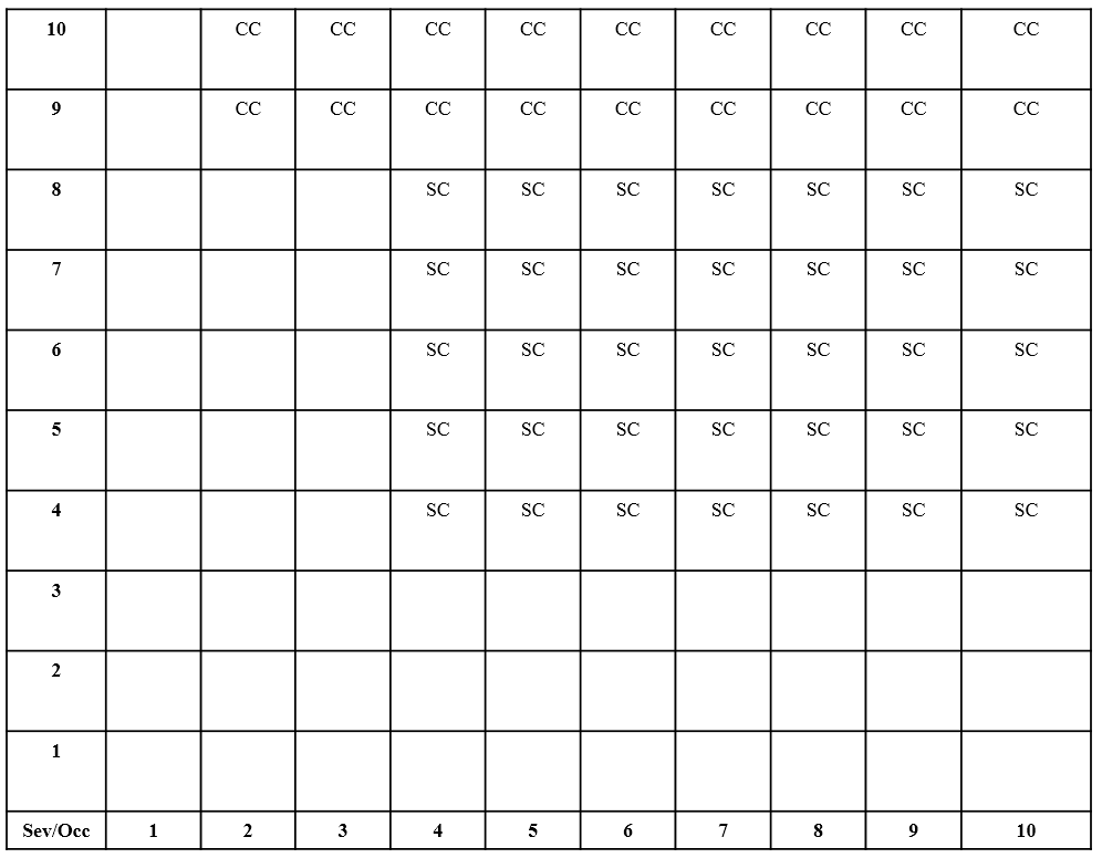
Figure 13: PFMEA Automotive Risk (Class Symbol) Table
If one were to use the Risk Table in Figure 13, the Severity Rating of 7 and Occurrence Rating of 2 found in the one-line Process FMEA example would not lead to the assignment of a symbol in the Class Column of the Process FMEA. This would indicate that the risk of ending up with a seal made out of the wrong material due to the wrong seal material being loaded into the mold when the only control was the Molding SOP which defined the material type to be loaded was acceptable.
Improper Use Of Process FMEA Class Column
It is very common for design engineers to assign a “Special Characteristic” symbol to a product characteristic specification on a product drawing. As an example, the Design FMEA found in this paper indicates that an improper seal material type can lead to water intrusion. As a means of communicating the importance of the seal material type to the manufacturing group, the design engineer might place an “SC” symbol next to the seal material type specification on the drawing.
Although the “SC” symbol on the drawing is an indicator of the consequences of the seal material type being incorrect, it provides no indication of the probability of the wrong seal material type being shipped as a result of a manufacturing error.
Typically there is an expectation on the part of the design engineer that the “SC” symbol will show up in the Class Column on every row of the Process FMEA where the “Produced seal material type is wrong” Failure Mode is present regardless of the occurrence rating on the row. When this happens, the accuracy of the Process FMEA as a risk management tool can be significantly reduced by highlighting product characteristics as high risk issues that the process has no problem meeting (Occurrence rating = 1). Although it is the responsibility of the design engineer to communicate the consequences of producing an out of spec condition, they should never identify which out of spec conditions get Class Symbols in the Process FMEA since they have no knowledge of process capability.
Elements Of 2001:2015 Supported By The Process FMEA
When performed correctly, the Process FMEA process forces a company to document the entire manufacturing process including purchased product receipt and handling, customer provided product receipt and handling (if applicable), equipment operation and maintenance and non-conforming product handling. When used correctly, the Process FMEA Process drives the creation of the Process Control Plan, Process Instructions, Operation Check Sheets and Process Validation Plan. The information contained in the Process FMEA is also critical to support process improvement and problem solving activities once the process is released for use.
When combined with the quality tools that it drives, the Process FMEA process directly fulfills or provides support for meeting the majority of the requirements found in following sections of the ISO 9001:2015 standard:
- 8.4 Control of externally provided products and services
- 8.5 Production and service provision
- 8.6 Release of products and services
- 8.7 Control on nonconforming process outputs, products and services
- 10. Improvement
